Tel: (804) 642-9296
Email: tadinc@earthlink.net
Tel: (804) 642-9296
Email: tadinc@earthlink.net

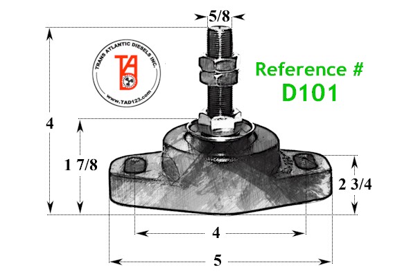
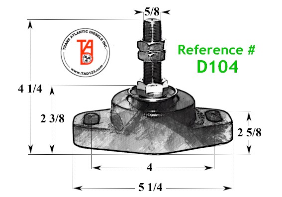
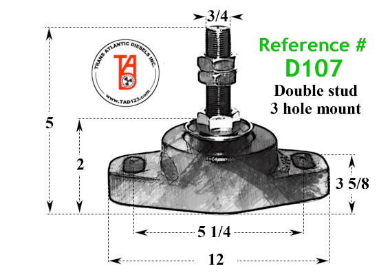
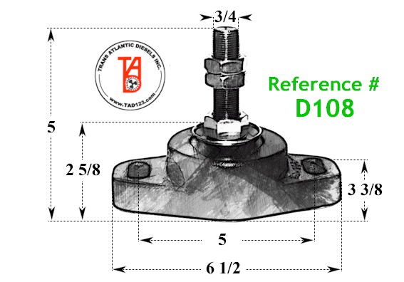
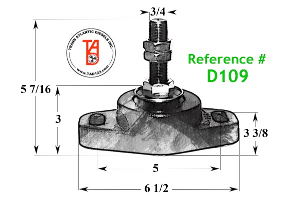
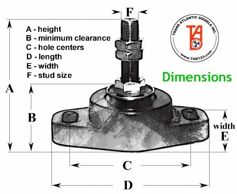
Compare the dimensions of your existing engine mount to the dimensions shown in the chart or in the slide show below (9 slides). When you have a match, take note of the large green Reference Number. Please reference that number when calling or emailing us.
| REF # | 4 Point Mount | A | B | C | D | E-width | F |
| D101 | 0-500 lbs | 4" | 1 ⅞" | 4" | 5" | 2 ¾" | ⅝" |
| D102 | 150-300 lbs | 4" | 2 ⅜" | 4" | 5" | 2 ¾" | ½" |
| D103 | 550-750 lbs | 4 7/16" | 2 ⅜" | 4" | 5" | 2 ¾" | ⅝" |
| D104 | 500-850 lbs | 4 ¼" | 2 ⅜" | 4" | 5 ¼" | 2 ⅝" | ⅝" |
| D105 | 350-550 lbs | 4 7/16" | 2 ⅜" | 4" | 5" | 2 ¾" | ⅝" |
| D106 | 850-1100 lbs | 4 ⅞" | 2 ⅜" | 4" | 5 ¼" | 2 ⅝" | ¾" |
| D107* | 2200-2600 lbs | 5" | 2" | 5 ¼" | 12" | 3 ⅝" | ¾" |
| D108 | 1800-2200 lbs | 5" | 2 ⅝" | 5" | 6 ½" | 3 ⅜" | ¾" |
| D109 | 1400-1600 lbs | 5 7/16" | 3" | 5" | 6 ½" | 3 ⅜" | ¾" |
| D107* - Double stud, three hole mount | |||||||
OR... Identify your engine mount using the images in the slide show marked D101 through D109
All measurements in inches.
Do you need to determine what engine mount will work with your current engine, based on your engine's weight and horsepower? Download the TAD Engine Mount Weight & HP Guide.
Click or tap on the button below to request prices or more information by email. Please remember to include the Reference Number of the engine mount you are inquiring about.
Request Purchasing Infoor call us at 804-642-9296
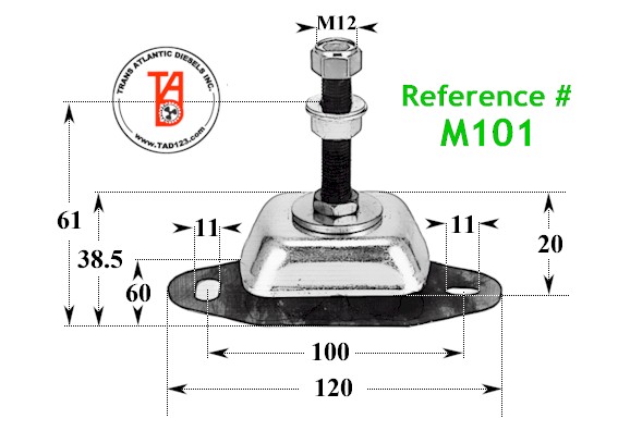
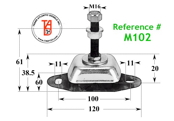
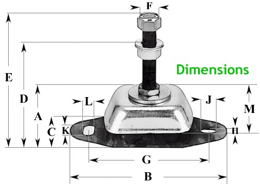
Compare the dimensions of your existing Cushyfloat engine mount to the dimensions shown in the chart or in the slide show below (3 slides). When you have a match, take note of the large green Reference Number. Please reference that number when calling or emailing us.
| REF # | A | B | C | D | E | F | G | H | J | K | L | M |
| M101 | 38.5 | 120 | 60 | 61 | 92.5 | M12 | 100 | 14 | 11 | 14 | 11 | 20 |
| M102 | 38.5 | 120 | 60 | 61 | 92.5 | M16 | 100 | 13 | 11 | 14 | 11 | 20 |
| M103 | 50 | 183 | 75 | 77 | 115 | M16 | 140 | 13 | 20 | 30 | 13 | 28 |
| All measurements in millimeters | ||||||||||||
OR... Identify your engine mount using the images in the slide show marked M101 through M103
All measurements in millimeters.
Click or tap on the button below to request prices or more information by email. Please remember to include the Reference Number of the engine mount you are inquiring about.
or call us at 804-642-9296
![]()
Mailing Address:
Trans Atlantic Diesels, Inc.
P.O. Box 70
White Marsh, VA 23183
Shipping Address:
Trans Atlantic Diesels, Inc.
5906 Fairfield Lane
Hayes, VA 23072
Tel: (804) 642-9296
Email: tadinc@earthlink.net
Quick Links: