Tel: (804) 642-9296
Email: tadinc@earthlink.net
Tel: (804) 642-9296
Email: tadinc@earthlink.net
The trolling valve enables low propeller speeds to be obtained by the use of an electrically controlled pressure reducing valve in the clutch pressure operating circuit. It also avoids the use of special oils for the gearbox when fitting the trolling valve.
All PRM units except PRM120/150 can be supplied with a factory fitted trolling valve, also a kit containing all necessary parts for operation and control is available for retro-fitting.
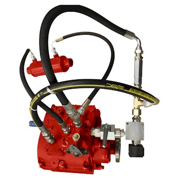
The trolling valve block is of aluminum alloy housing the on/off and pressure reducing solenoid valves. The solenoid valves are hermetically sealed and supplied with DIN 43650 type connectors. (Figure 1 of the circuits and assembly diagrams shows the basic circuit diagram - this is available to download at the bottom of this page).
When using the trolling valve it will be necessary to change the control valve spool MT4656 with MT1538, This is provided in the kit.
The operating lever is a Morse type NB unit with locking handle. The housing contains the electrical circuits for operating the trolling valve which again are encapsulated to provide a waterproof seal. The lever is complete with:
The trolling valve is connected as shown in figure 1 of the circuits and assembly diagrams (available for download at the bottom of this page) and operates as follows:
Prices are made available by email or phone.
or call us at 1-804-642-9296 for more information.
![]()
Mailing Address:
Trans Atlantic Diesels, Inc.
P.O. Box 70
White Marsh, VA 23183
Shipping Address:
Trans Atlantic Diesels, Inc.
5906 Fairfield Lane
Hayes, VA 23072
Tel: (804) 642-9296
Email: tadinc@earthlink.net
Quick Links:
